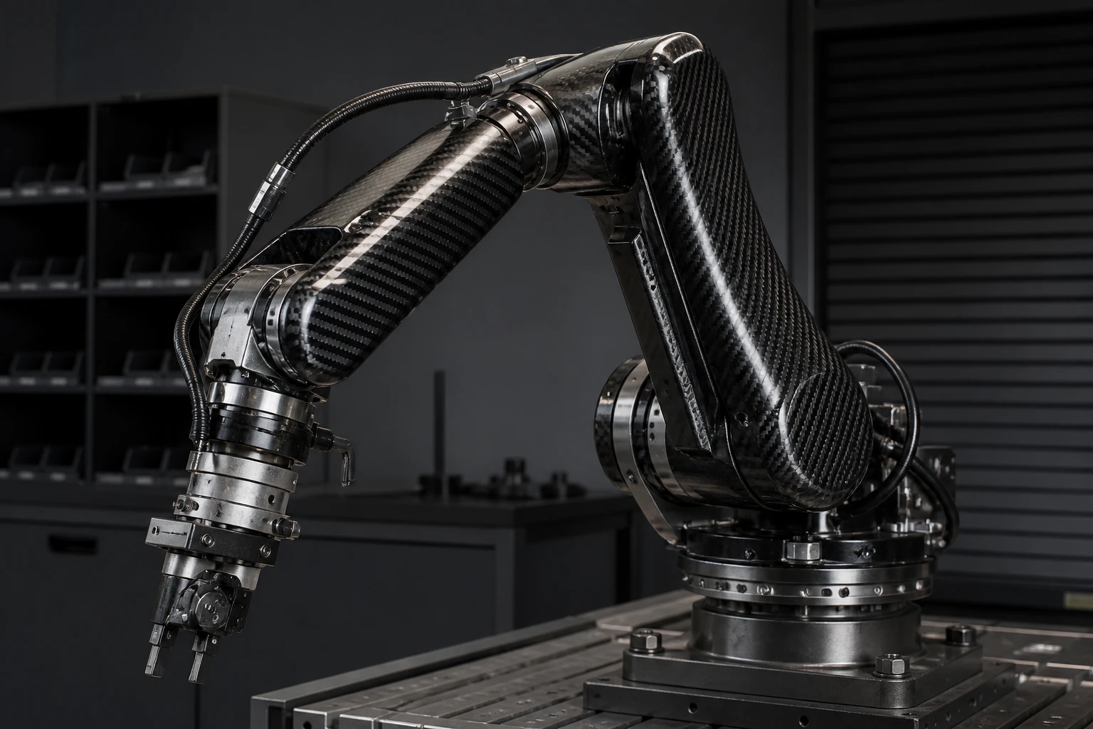
Robotics & Automation
Lightweight brackets, panels, mounts, and drawing-based structural components.

 DRAWING-BASED CNC PROCESSING · OEM SUPPORT
CARBON FIBER MACHINING SERVICE
Drawing-based CNC machining and secondary processing for carbon fiber sheets, plates, tubes and custom components.
Share the controlled drawing, material form, quantity, critical features, inspection expectations, and delivery needs for a project-specific manufacturing review.
WHAT WE MACHINE
Geometry, construction, visible surfaces, assembly features, and inspection needs are reviewed together. Final feasibility is project dependent.
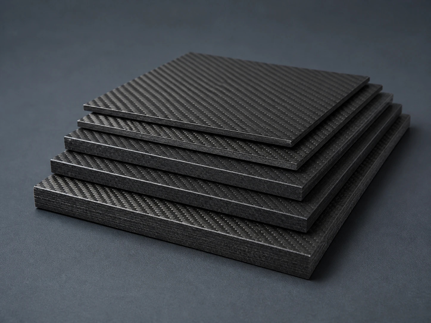
Flat laminate stock reviewed together with the finished profile, holes, slots, edges, and inspection expectations.
Tube cutting and secondary features reviewed against the tube construction, interfaces, drawing, and intended assembly.
Existing laminate forms assessed for feature access, edge requirements, visible faces, and project-specific acceptance criteria.
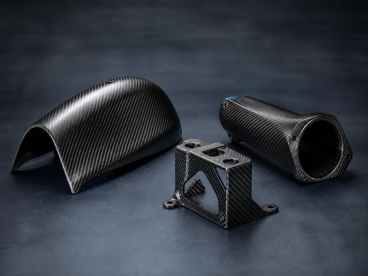
Custom component geometry reviewed from the controlled drawing, selected material form, quantity, and end-use requirements.
CNC OPERATIONS
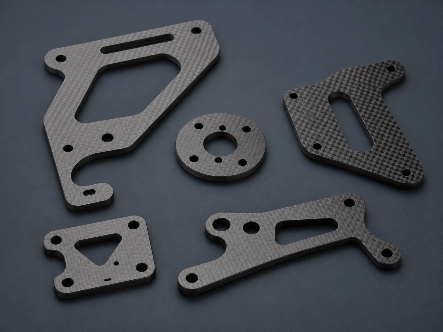
Finished profiles and cut-to-drawing geometry reviewed for the selected carbon fiber form.
Drilled features assessed with location, edge distance, assembly function, and inspection expectations.
Hole geometry and position reviewed from the controlled drawing and mating-part requirements.
Slots and openings reviewed for geometry, access, edge condition, and intended function.
Functional and visible edge requirements defined before processing and final inspection.
Internal and external contours reviewed against part geometry and material construction.
Profiles, cutouts, and combined features assessed as one finished component requirement.
DRAWING / RFQ CHECKLIST
Send the information already available. Missing or project-dependent details can be clarified during drawing and process review.
FROM DRAWING TO FINISHED PART
Confirm revision, finished geometry, critical features, quantity, and open technical questions.
Review the material form, construction, feature access, edges, and project-dependent processing route.
Process the agreed cutting, drilling, slots, contours, and drawing-based features.
Check specified dimensions, feature condition, edges, and visible surfaces against agreed requirements.
Verify product protection, identification, quantity, and shipment requirements before dispatch.
APPLICATION CONTEXT
These categories illustrate typical application contexts only. They are not presented as customer projects or performance claims.
Lightweight brackets, panels, mounts, and drawing-based structural components.
Machined panels, covers, interfaces, and equipment-facing components.
Custom profiles with holes, slots, contours, and defined edge requirements.
Lightweight fixture elements and support components made to controlled geometry.
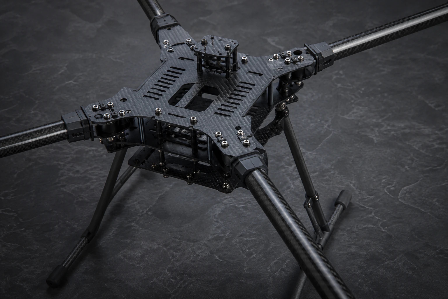
Panels, frames, brackets, and lightweight structural parts for drawing review.
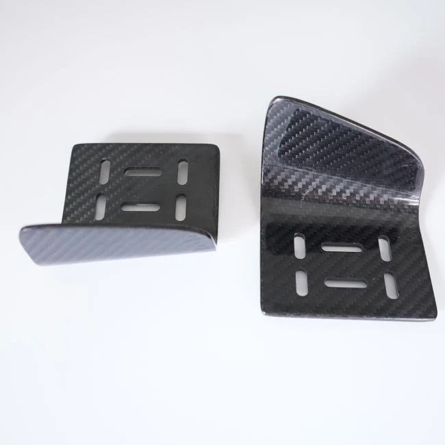
Project-specific parts for machinery, instruments, and engineered assemblies.
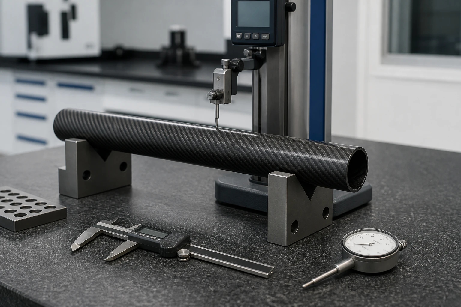 INSPECTION VISUAL · AUTHORIZED SUPPLIER MEDIA
QUALITY & INSPECTION
Key processing and part-condition checkpoints follow the agreed drawing and project requirements.
Specified dimensions and machined features are checked against agreed acceptance criteria.
Visible surfaces, feature condition, and edges are reviewed before packing.
Protection, identification, quantity, and packing requirements are checked before shipment.
BUYER FAQ
Yes. Carbon fiber sheets, plates, tubes, laminated components, and drawing-based custom parts can be reviewed for CNC processing. Feasibility and the processing route are confirmed for the selected material form and finished geometry.
The inquiry form accepts PDF, STEP, STP, DXF, DWG, JPG, and PNG files, up to 20 MB each and three files per inquiry.
Yes. Holes, slots, cutouts, contours, and edge requirements can be reviewed from the drawing. Feature feasibility and acceptance criteria are project dependent.
Yes. CNC processing can be reviewed for carbon fiber sheets, plates, and tubes. Tube construction, feature access, interfaces, and edge requirements are considered during drawing review.
Send the latest drawing or CAD file, material form, overall dimensions, thickness where relevant, hole or slot geometry, edge requirements, quantity, inspection expectations, packing needs, and shipment destination.
Prototype and production requirements can both be reviewed. Material, processing route, inspection expectations, packing, and quantity are considered together before a supply plan is confirmed.
Finished parts receive in-process checks, dimensional inspection, and visual inspection against the agreed project requirements. Protection, identification, quantity, and packing are verified before shipment.
START A CNC MACHINING PROJECT